Hardware Setup
This guide explains the hardware required for the ESP32 Distance Sensor Workshop and how to wire up the components.
Note
QEMU Alternative: If you don’t have hardware available, you can complete the workshop using QEMU emulation. See Getting Started with the Workshop for QEMU instructions.
Required Hardware
ESP32 WROOM-32F Development Board
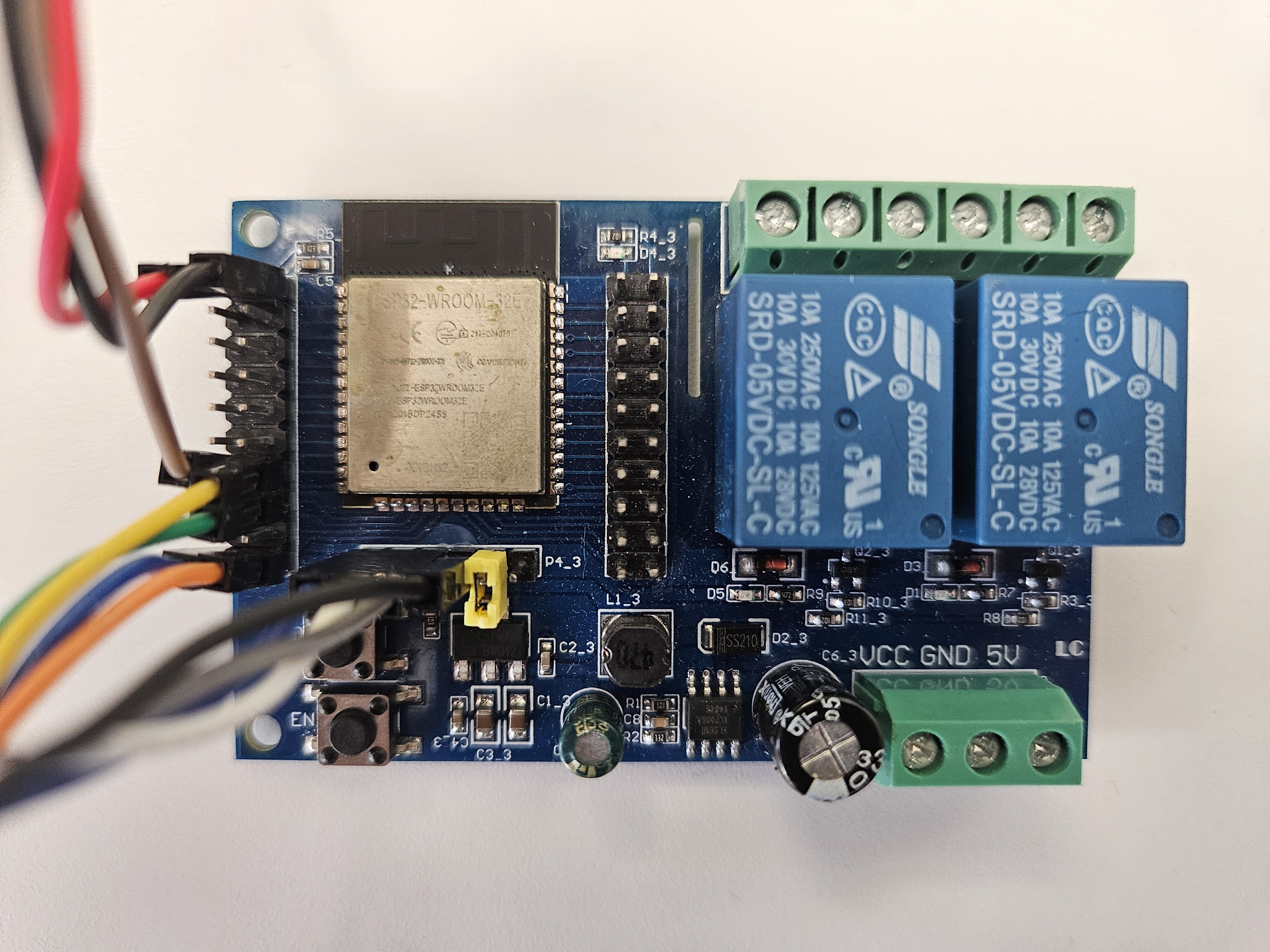
Specifications:
Microcontroller: ESP32-WROOM-32F (4MB flash)
WiFi: 2.4 GHz 802.11 b/g/n
Bluetooth: Classic + BLE
GPIO Pins: 38 available
Operating Voltage: 3.3V logic, 5V power input
Current: Up to 500mA (typical)
Note
Board Shown: The board in the image is an ESP32 Relay X2 with two onboard relays and wide input voltage support (5-60V), ideal for 12V/24V/48V systems like solar batteries.
Any ESP32 board works! You can use standard ESP32 DevKit, NodeMCU-32S, or similar boards.
USB-to-Serial Adapter:
If your ESP32 board does not have a built-in USB port (like the Relay X2), you will need an external USB-to-serial adapter:
CH340-based adapter (most common)
CP2102-based adapter (also works)
FTDI-based adapter (higher quality)
Most modern ESP32 development boards have built-in USB, so you can skip the external adapter.
USB Serial Adapter (Optional)

When Required:
Your ESP32 board lacks onboard USB
Example: ESP32 Relay X2
Features:
Chipset: CH340G or CH340C
Interface: USB-A to TTL serial (3.3V/5V)
Pins: TX, RX, GND, 5V, 3.3V
Compatible: Windows, macOS, Linux (driver required)
Warning
Driver Installation: CH340 adapters may require driver installation on Windows/macOS. Download from: CH340 Drivers
HC-SR04 Ultrasonic Distance Sensor
How It Works:
The HC-SR04 ultrasonic distance sensor measures distance by emitting an ultrasonic pulse and measuring the time it takes for the echo to return:
Trigger: ESP32 sends 10μs pulse to trigger pin
Ultrasonic Burst: Sensor emits 8×40kHz ultrasonic pulses
Echo: Sound reflects off object and returns
Echo Pulse: Sensor sets echo pin HIGH for time proportional to distance
Calculate: ESP32 measures pulse width and calculates distance
Specifications:
Range: 2cm to 400cm (0.8” to 157”)
Accuracy: ±3mm
Angle: ~15° cone
Operating Voltage: 5V
Trigger Signal: 10μs TTL pulse
Echo Signal: TTL output (0V to 5V)
Current: 15mA (measurement), 2mA (idle)
Tip
Best Range: 10cm to 300cm for reliable measurements. Outside this range, readings may be unstable or timeout.
WS2812 Addressable LED Strip
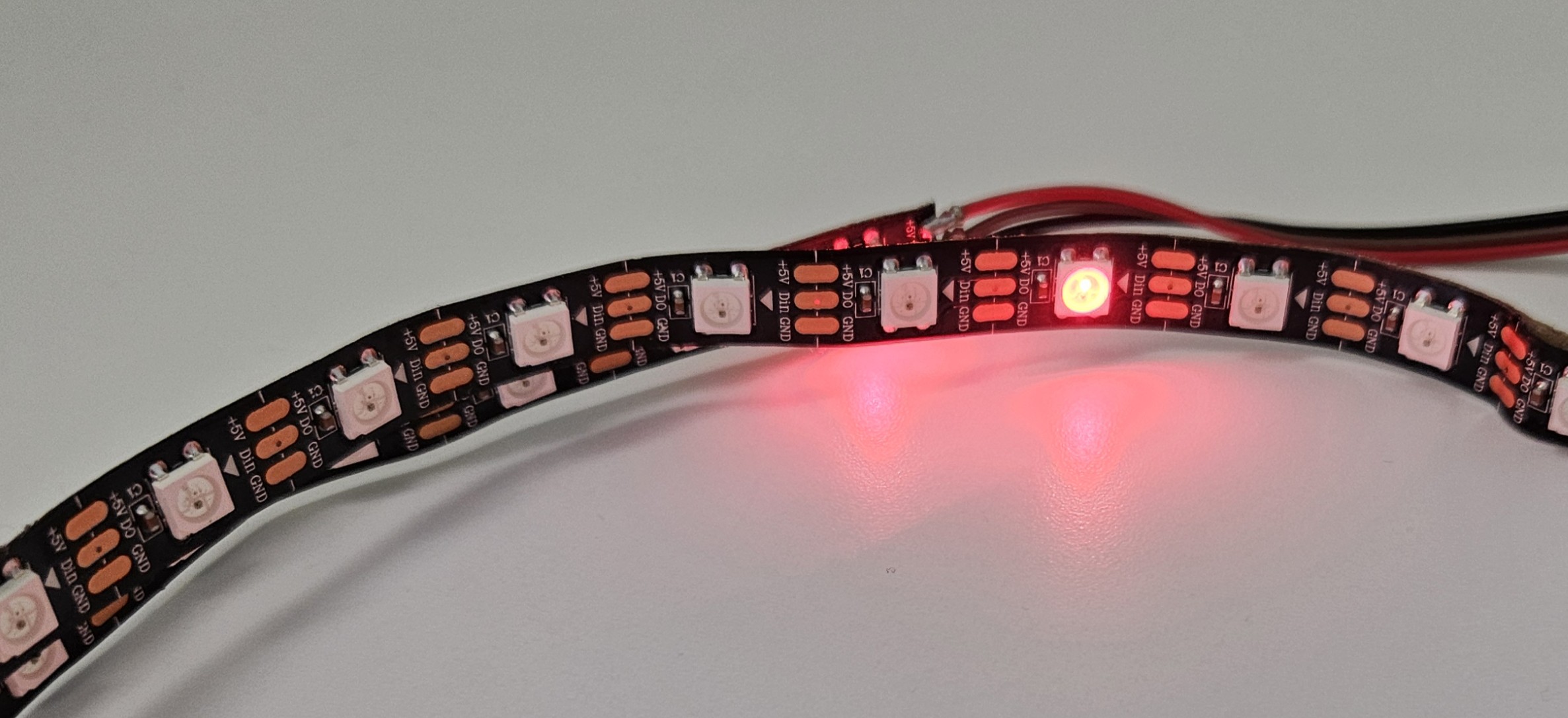
What Are WS2812 LEDs?
The WS2812 is an addressable RGB LED (also called “NeoPixels” by Adafruit) where each LED can be individually controlled for color and brightness using a single data line.
How It Works:
Each LED contains a tiny controller chip
LEDs are daisy-chained: data flows from first to last LED
ESP32 sends color data using precise timing (800kHz protocol)
RMT (Remote Control Transceiver) hardware generates exact timing
Specifications:
LEDs per strip: 40 recommended (30-60 works too)
Voltage: 5V DC
Current per LED: ~60mA at full white brightness
Total current (40 LEDs): ~2.4A max (600mA typical)
Data protocol: WS2812B (single wire)
Refresh rate: 30-60 Hz (smooth animations)
Warning
Power Requirements: 40 LEDs at full brightness draw 2.4A! Most USB ports only provide 500mA-900mA.
Solution:
Keep brightness low (~25%) when USB-powered
Use external 5V power supply for full brightness
Connect power supply ground to ESP32 ground
Tip
LED Strip Length:
40 LEDs (1 meter) - Recommended for workshop
30 LEDs - Works fine, less resolution
60 LEDs - More detail, requires external power
Additional Required Items
USB Cable: USB-A to Micro-USB or USB-C (depends on your board)
Breadboard: Half-size or full-size for prototyping
Jumper Wires: Male-to-male, male-to-female (mixed pack)
Power Supply (optional): 5V 3A for LED strip if needed
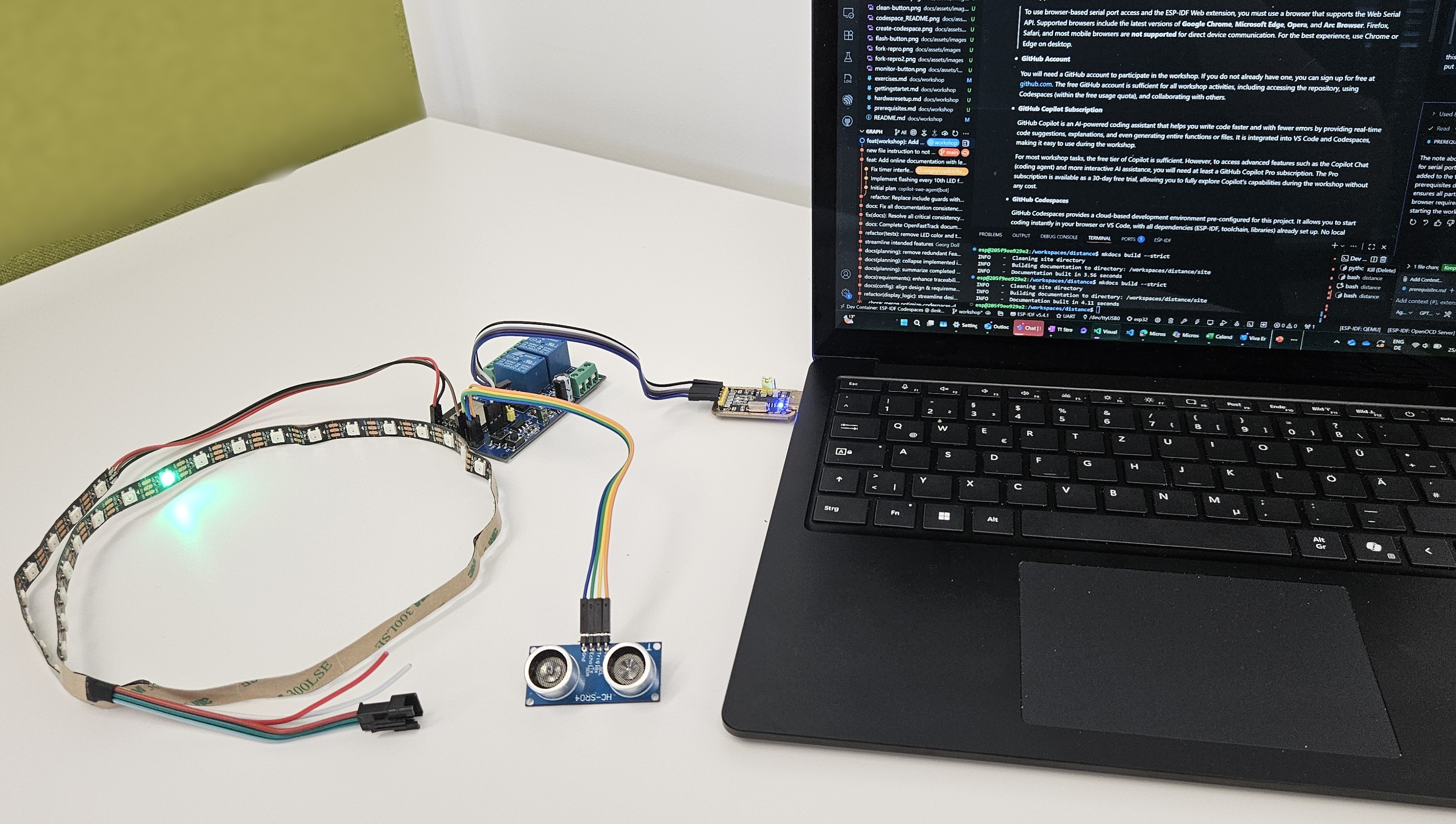
Wiring Diagram
Complete Connection Overview
Connect all components to the ESP32 according to the pin configuration below.
Pin Configuration Table
HC-SR04 Ultrasonic Sensor Connections:
Sensor |
ESP32 GPIO |
Purpose |
|---|---|---|
VCC |
5V |
Power supply |
GND |
GND |
Ground |
TRIG |
GPIO 13 |
Trigger pin (output) |
ECHO |
GPIO 14 |
Echo pin (input) |
See also
Requirements Traceability: See Distance Sensor Requirements for detailed sensor specifications and rationale.
WS2812 LED Strip Connections:
LED Strip |
ESP32 GPIO |
Purpose |
|---|---|---|
5V |
5V or External PSU |
Power supply |
GND |
GND |
Ground (common) |
DIN |
GPIO 12 |
Data input (RMT) |
See also
Requirements Traceability: See LED Controller Requirements for LED strip specifications and control protocol.
Warning
Important: Connect DIN (data input), not DOUT (data output)! LED strip is directional—arrows show data flow direction.
USB Serial Adapter Connections (If Required):
Serial Adapter |
ESP32 GPIO |
Notes |
|---|---|---|
5V |
5V |
Power input |
GND |
GND |
Common ground |
TX |
RX (GPIO3/U0RXD) |
Crossed connection |
RX |
TX (GPIO1/U0TXD) |
Crossed connection |
Note
TX/RX Crossover: The serial adapter’s TX connects to ESP32’s RX, and serial adapter’s RX connects to ESP32’s TX. This is standard serial wiring!
Schematic Diagram
Complete System Wiring:
+-------------------+         +-------------------------+
|   USB Serial      |         |      ESP32 Board        |
|   Adapter (CH340) |         |    (ESP32 WROOM-32F)    |
+-------------------+         +-------------------------+
|                   |         |                         |
|   5V   -----------+---------+--- 5V                   |
|   GND  -----------+---------+--- GND                  |
|                   |         |                         |
|   RX   -----------+--\   /--+--- RX (GPIO3/U0RXD)     |
|                   |   \ /   |                         |
|                   |   / \   |                         |
|   TX   -----------+--/   \--+--- TX (GPIO1/U0TXD)     |
|                   |         |                         |
+-------------------+         +-------------------------+
                              |                         |
                              +--- GPIO 12 --> LED DIN  |
                              |                         |
                              +--- GPIO 13 --> HC TRIG  |
                              +--- GPIO 14 <-- HC ECHO  |
                              |                         |
                              +--- 5V  -----> HC VCC    |
                              +--- GND -----> HC GND    |
                              |                         |
                              +--- 5V  -----> LED 5V    |
                              +--- GND -----> LED GND   |
                              +-------------------------+
Note: TX/RX lines are crossed between adapter and ESP32.
Step-by-Step Assembly
Follow these steps to wire your hardware safely:
Step 1: Prepare Workspace
Clear surface - Use non-conductive surface (wood, plastic)
Organize components - Lay out all parts
Check tools - Have wire cutters, strippers ready (if needed)
Disconnect power - Ensure nothing is plugged into USB
Step 2: ESP32 to Breadboard
Insert ESP32 into breadboard (straddle center gap)
Ensure all pins accessible on both sides
Leave room for sensor and LED connections
Tip
Breadboard Tip: Place ESP32 near one end to leave more space for wiring components on the other side.
Step 3: Connect HC-SR04 Sensor
VCC (sensor) → 5V (ESP32) - Use red wire
GND (sensor) → GND (ESP32) - Use black wire
TRIG (sensor) → GPIO 13 (ESP32) - Use yellow/orange wire
ECHO (sensor) → GPIO 14 (ESP32) - Use blue/green wire
Warning
Voltage Warning: HC-SR04 requires 5V power but outputs 5V logic on echo pin. ESP32 GPIO pins are 5V-tolerant, but verify your specific board datasheet!
Step 4: Connect WS2812 LED Strip
5V (LED) → 5V (ESP32) or External PSU - Use thick red wire
GND (LED) → GND (ESP32) - Use thick black wire (common ground!)
DIN (LED) → GPIO 12 (ESP32) - Use data wire (any color)
Important
Check Directionality: LED strips have arrows showing data flow direction. Connect DIN (data input) side to ESP32, not DOUT (data output) side!
Warning
Power Consideration: If using USB power only:
Keep LED brightness at 25% or lower in code
Reduce number of LEDs if flickering occurs
Monitor ESP32 for overheating
For full brightness: Use external 5V 3A power supply connected to LED strip’s 5V/GND, and connect ESP32 GND to power supply GND (common ground).
Step 5: Connect USB Serial Adapter (If Required)
Note
Skip this step if your ESP32 board has built-in USB!
5V (adapter) → 5V (ESP32) - Power supply
GND (adapter) → GND (ESP32) - Common ground
TX (adapter) → RX/GPIO3 (ESP32) - Crossed!
RX (adapter) → TX/GPIO1 (ESP32) - Crossed!
Step 6: Double-Check All Connections
Before plugging in USB:
✓ Power connections - All 5V and GND correct ✓ No short circuits - No wires touching ✓ Correct GPIO pins - Match table above ✓ LED strip direction - DIN not DOUT ✓ TX/RX crossed - If using serial adapter ✓ Secure connections - No loose wires
Danger
Pro Tip: Double-check your wiring before plugging the USB Serial Adapter into your PC or laptop—better safe than sorry!
Incorrect wiring can damage components!
Step 7: Connect USB and Test
Plug USB cable into computer
Watch for power LED on ESP32 (should light up)
Check for smoke/heat - Disconnect immediately if detected
Proceed to flashing - See Getting Started with the Workshop Step 7
Safety Guidelines
Important Safety Notes:
Electrical Safety:
Use proper 5V power supply (do not exceed voltage)
Avoid short circuits (especially 5V to GND)
Keep liquids away from electronics
Work on non-conductive surface
Component Safety:
Do not exceed LED strip current rating
Do not connect/disconnect while powered
Handle sensors gently (ultrasonic transducers are fragile)
Avoid reverse polarity on power connections
Personal Safety:
Do not touch components while powered
Unplug before making wiring changes
Keep workspace organized
Disconnect power if anything feels hot
Testing Your Hardware
Before Running Full Firmware:
Power Test: Plug in USB, check ESP32 power LED
LED Test: Flash firmware, watch for startup LED sequence
Sensor Test: Hold hand in front of sensor, watch LEDs respond
Serial Test: Open monitor, verify distance readings appear
WiFi Test: Connect to “ESP32-Distance-Sensor” AP
Tip
Quick Hardware Test: Flash the firmware and watch for LED startup test. If you see red, green, then blue sweeping across the strip, your hardware is working! See Startup Test Requirements for details.
Troubleshooting Hardware Issues
Common Problems:
No power LED:
Check USB cable (data + power, not just charging cable)
Try different USB port
Verify ESP32 is seated properly in breadboard
LEDs not lighting:
Check 5V and GND connections to LED strip
Verify GPIO 12 connection to DIN (not DOUT)
Confirm LED strip direction (arrows)
Lower brightness in code if USB-powered
Check for sufficient power supply current
Sensor not responding:
Verify 5V power to sensor VCC
Check GND connection
Confirm GPIO 13 → TRIG and GPIO 14 → ECHO
Ensure nothing blocking sensor (<15cm minimum)
Test in open space away from objects
Serial port not found:
Install CH340/CP2102 drivers (Windows/macOS)
Check Device Manager (Windows) or
ls /dev/tty*(Linux)Try different USB cable
Verify TX/RX connections crossed correctly
ESP32 reboots continuously:
Power supply insufficient (add external 5V for LEDs)
Short circuit present (disconnect and recheck wiring)
Faulty component (test each component individually)
Next Steps
Once your hardware is assembled and tested:
Return to Getting Started: Continue at Getting Started with the Workshop Step 7 (Flash firmware)
Start Workshop Exercises: Proceed to Workshop Exercises for hands-on challenges
Understand the System: Read the Project Introduction and Requirements Documentation
Need Help?
Check Development Guide for detailed component guides
Review requirements: Requirements Documentation
Ask facilitator (if in guided workshop)
GitHub Issues: esp32-distance/issues
—
Hardware ready? Great! Head back to Getting Started with the Workshop and flash your firmware! 🚀